


Vintage Air Retrofit
Page 2 of 4 •  1, 2, 3, 4
 ![]()
Re: Vintage Air Retrofit
![]() by thatfnthing Mon May 21, 2012 10:35 am
by thatfnthing Mon May 21, 2012 10:35 am

thatfnthing- Donating Member

- Street Cred : 65
Re: Vintage Air Retrofit
![]() by thatfnthing Wed May 30, 2012 7:43 pm
by thatfnthing Wed May 30, 2012 7:43 pm
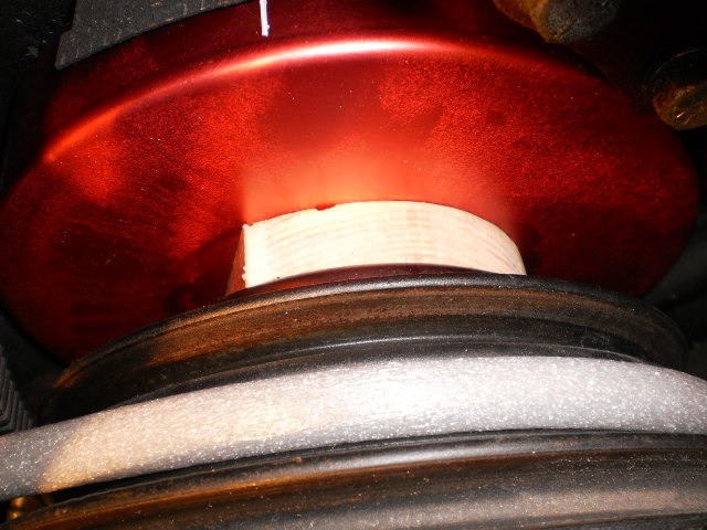
So the crank spacers I ordered turned out to be mis-advertised on thickness -- two sets should have equaled 3/4", but instead they came only to 1/2". Got to order one more set, but in the meantime I cheated for mockup with a 3/4" wood spacer between the crank pulley and the balancer:
Alan Grove Components came to my rescue again on the alternator bracket changes -- when I told them what I was trying to do, the guy sent me a bunch of lengths of the bar stock leftover from the machine shop for just the price of shipping.
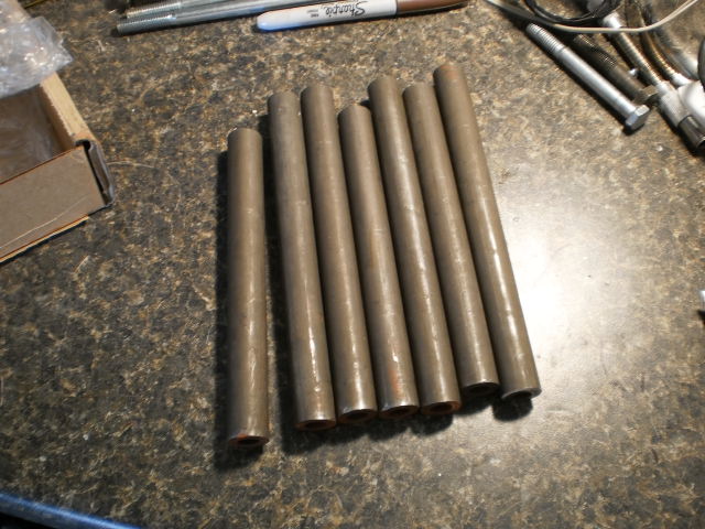
This allowed me to make wider spacers between the inner and outer brackets for the alternator, which located the alt pulley in line with the outer groove of the crank pulley while still leaving plenty of room for the fuel lines and adjusting the P/S pump, but coming up just shy of the ABS modulator. It's starting to look a bit like a Rube Goldberg device crossed with a set of monkey bars, but it's solid and should work. Now my wife says I need to polish it all.
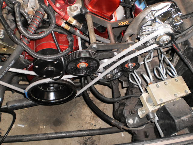
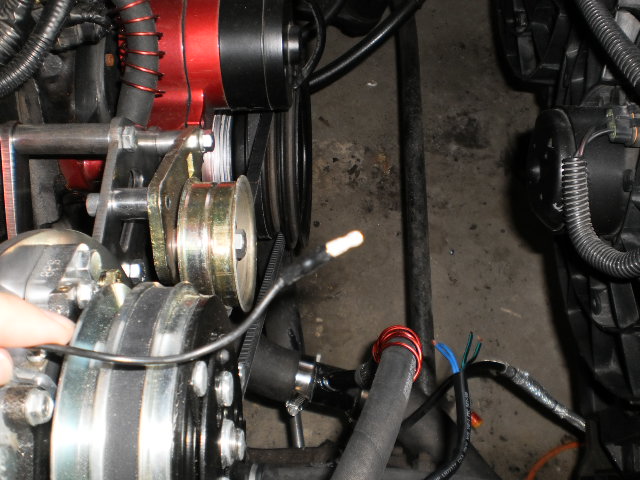
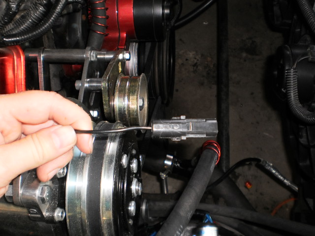
Last part is to route the belt. I spent some time at the boneyard and came home with a bunch of idler pulleys (none of them quite fit the bill, but I learned a lot about how the various factories implemented them), and it told me what I needed to do here. This shot shows the completed alt bracket, how the belt will route, and where my idler pulleys need to be.
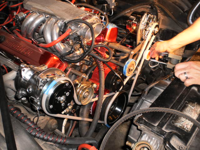
The one in blue tape is from an Isuzu Rodeo and is almost the right size, so I'm using it as a stand-in until I can get the correct 4" pulley, and the roll of teflon tape in my hand approximates the size and position of the one I will need to keep the belt away from the P/S pulley. Here's a closer shot:
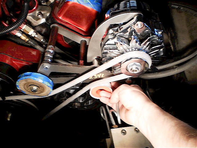
It was a trick and a half to find the right size pulleys and took some digging on the web. Auto parts sites expect you to know the make/model of the vehicle beforehand -- you can't just shop by size.
So these are on order now, but may take a few days. So next up, condenser!
thatfnthing- Donating Member
- Street Cred : 65
Re: Vintage Air Retrofit
![]() by 77mali Wed May 30, 2012 8:19 pm
by 77mali Wed May 30, 2012 8:19 pm
With all the thought & work/research involved in your build, I gotta say that I'm impressed. You should sell the info as a blueprint (not to us here of course).

The, Enter: year/make/model thing, drives me nuts.

77mali- Donating Member
- Street Cred : 62
Re: Vintage Air Retrofit
![]() by thatfnthing Thu May 31, 2012 2:11 pm
by thatfnthing Thu May 31, 2012 2:11 pm
My setup is unique in a few ways, such as my electric water pump, so many people won't have some of the issues I do. But in case someone ever does have something off beat, they'll at least know it can be done.
As for make and model, I never know how to answer that anymore -- there are so many parts from other makes and models that it only looks like a Monte now. I read an editorial in one of the car mags that said you know you're a hardcore car guy if the parts counter rep asks for make and model and you just stare at him blankly.
thatfnthing- Donating Member
- Street Cred : 65
Re: Vintage Air Retrofit
![]() by thatfnthing Wed Jun 06, 2012 8:18 pm
by thatfnthing Wed Jun 06, 2012 8:18 pm
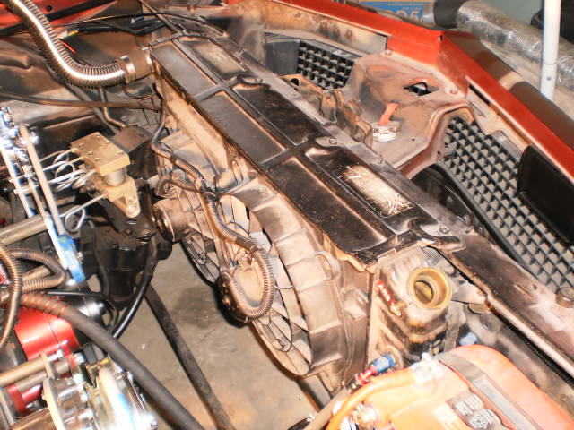
...to get at the factory condenser that's been hiding in there for about 40 years:
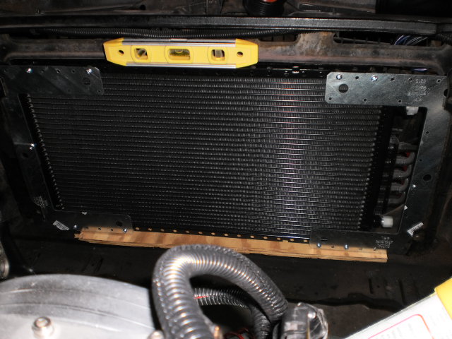
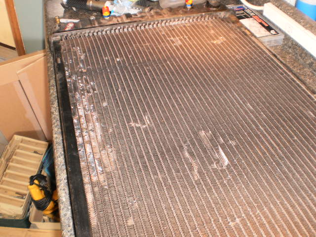
The factory unit is immense compared to the VA unit, as you can see in this shot:
The condenser is mounted to two large brackets (the left side of which has the old drier mounted to it), which in turn are mounted to the radiator brace with four isolators...
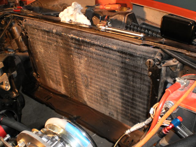
...only one of which surrendered without a fight. Anyway, with the original condenser out...
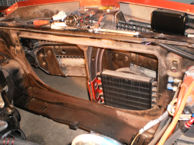
...it's easy to see where the new condenser won't come close to bridging the gap.
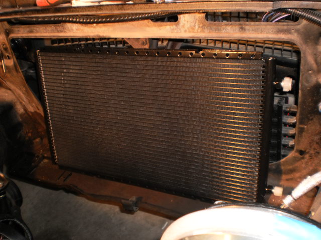
My concern here is airflow. With the gaps all the way around, I can picture the air mostly just flowing around it rather than through it. So rather than mount it directly to the radiator brace, I think it will make more sense to get it as close the radiator as possible so the fans pull the air through both.
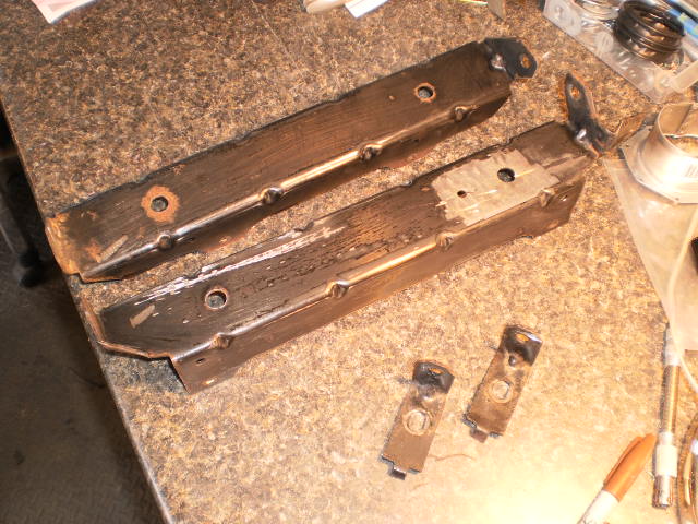
This in turn means I'll be best off re-using the original factory brackets on either end, so I ground off the drier mount on the left one, and cleaned and sanded them in preparation for paint.
The VA-supplied mounting tabs were too short and too flimsy to bridge these gaps:
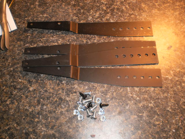
So I got some 1/8" 6x6 steel L-brackets from Home Depot, and laid the whole thing out on the workbench. The blue tape has the measurements from the actual radiator brace so I can tell where the left and right brackets need to sit in relation to each other, which in turn allows me to properly position the condenser between them.
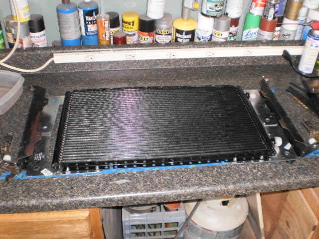
Since the original brackets are 2 1/4" wide for the old condenser, and the new condenser is only 3/4" wide, I am assembling it face down so that when I put it in, the condenser will be closer to the radiator.
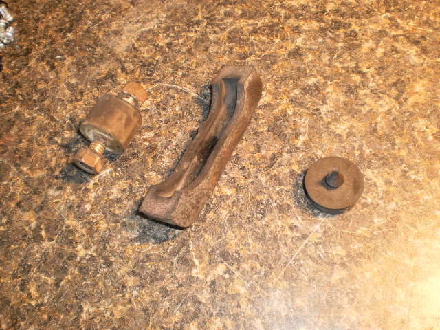
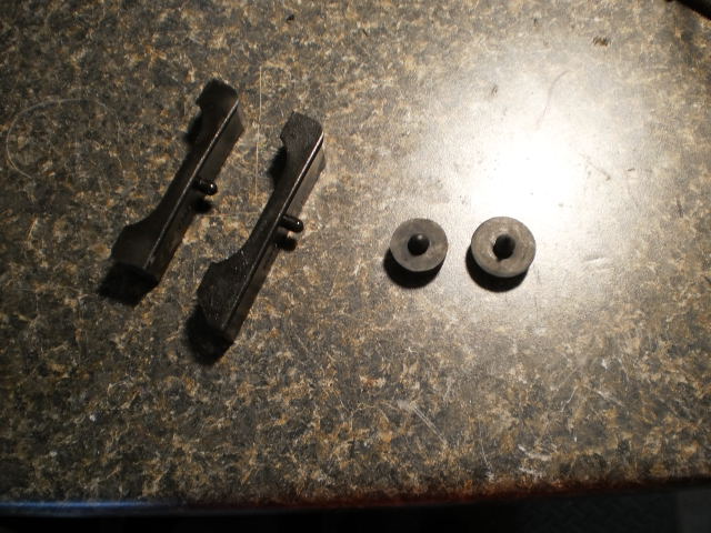
Meantime, I need new isolators and a couple other rubber parts to replace a damaged radiator pad and a couple of the disk-shaped rubber bumpers that further isolate the condenser from vibration.
I naively hoped I could find these locally, so I went to three stores.
Store 1: "Not a chance."
Store 2: "Whaddya workin' on, something from the Sixties?"
Store 3: "I think I might be able to special order them."
No thanks, I can do that myself, and have them show up at my door.
thatfnthing- Donating Member
- Street Cred : 65
Re: Vintage Air Retrofit
![]() by 77mali Wed Jun 06, 2012 11:11 pm
by 77mali Wed Jun 06, 2012 11:11 pm
77mali- Donating Member
- Street Cred : 62
Re: Vintage Air Retrofit
![]() by ant7377 Wed Jun 06, 2012 11:11 pm
by ant7377 Wed Jun 06, 2012 11:11 pm

ant7377- G3GM Addict

- Street Cred : 36
Re: Vintage Air Retrofit
![]() by thatfnthing Wed Jun 06, 2012 11:25 pm
by thatfnthing Wed Jun 06, 2012 11:25 pm
Thanks for the support, guys! I just hope I can get it done while I can still use it!
thatfnthing- Donating Member
- Street Cred : 65
Re: Vintage Air Retrofit
![]() by thatfnthing Sun Jun 17, 2012 8:21 pm
by thatfnthing Sun Jun 17, 2012 8:21 pm
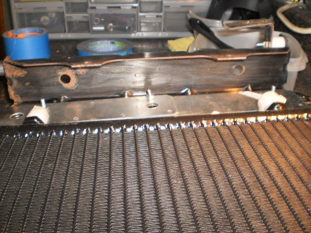
The rubber isolators from Jegs fit the bill perfectly. The Prothane radiator pads turned out to be nicer than the stock rubber, but two needed a little triimming, and the SoffSeal rubber pad was the right thickness (albeit slightly smaller diameter -- it's the left one) for the condenser bracket. Since no one will see it, I'm calling it close enough for jazz:
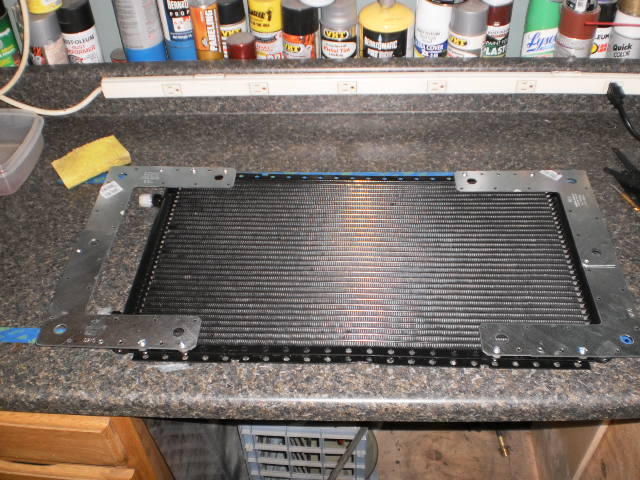
Flipping the condenser over shows a better view of the bracketry. Note that the condenser itself is slightly offset to the driver's side -- I wanted a little more room to make the connections.
Next step was to get it at the right height (about 3/8" above the core support, supported with plywood), and level, then mark the places where it met up with the factory side brackets.
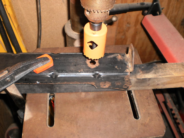
Next item to address is the refrigerant lines. Note the outlets from the condenser just don't quite line up with the holes in the brackets...
...so it's time to break out the 1 1/2" hole saw.
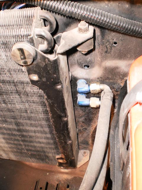
Rather than try to wrestle the actual hoses around the side of the radiator, I opted for a couple of the VA premade 12" -6 and -8 lines and broke out the tubing benders. I originally wanted to do something fancier and have the two lines come out right next to each other, but my benders couldn't make a tight enough radius, so I went for the traditional L shape:

I attached the lines but left the end caps in place to prevent errant crud from getting in them until ready for the actual hoses. Along the way I gave the L brackets a coat of red anodize just for a little pizzazz, then permanently mounted the side brackets and reinstalled the rubber isolators.
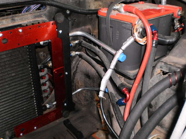
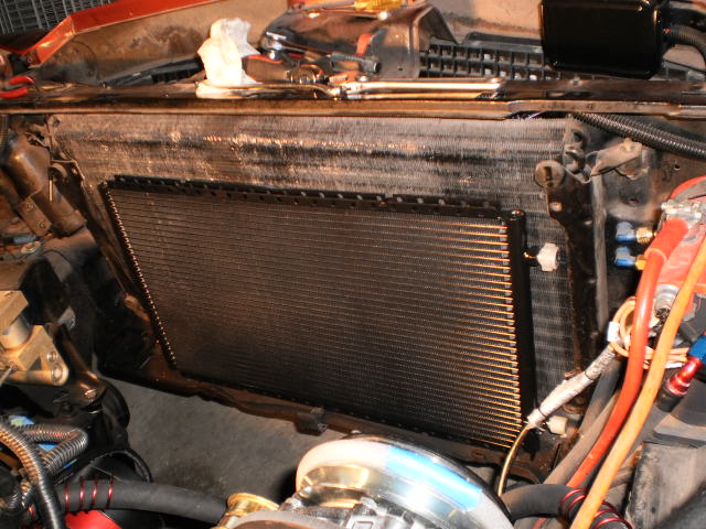
Then we test fit the radiator to make sure the lines don't conflict.
The condenser is done, but before buttoning it all up, I took the time to lightly wire brush the accumulated dandelion fuzz out of the front side of the radiator...

... and got out the pick to straighten the various bent fins on the back side. In some cases it helped to put a light under it. When I got the fins straight enough to see light I could be sure it would flow air.
Finally, I cleaned up the fans, stripped and repainted the top plate and put it all back together.
Last edited by thatfnthing on Sun Jun 17, 2012 8:38 pm; edited 1 time in total
thatfnthing- Donating Member
- Street Cred : 65
Re: Vintage Air Retrofit
![]() by thatfnthing Sun Jun 17, 2012 8:34 pm
by thatfnthing Sun Jun 17, 2012 8:34 pm
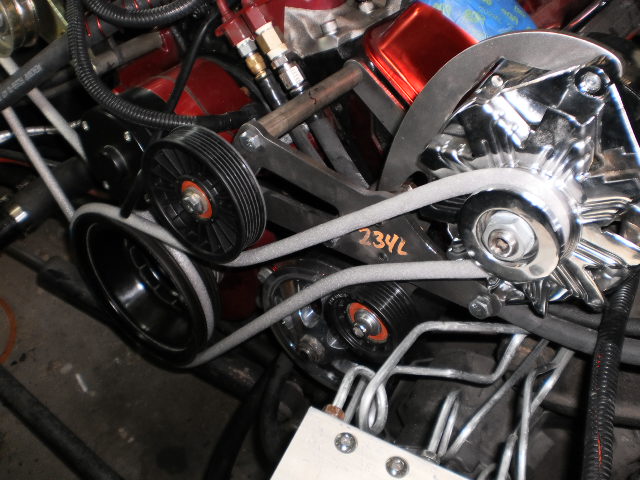
The larger inboard pulley is 109mm. I wanted about a 104mm, but I was unable to locate a flanged pulley of that size. There were plenty of smooth ones, but the nearest size down in a flanged pulley is 96mm, which was too small. As it is it will work, but there is only 1mm clearance between the pulley flange and the water pump motor.
The smaller pulley is 59mm, and is mounted on the bracket ear I had previously cut off the alternator adjustment arm. I added two threaded holes to the main bracket -- 3/8" as a pivot, and 5/16" as an adjustment bolt so the pulley can be adjusted in an arc if need be and retightened.
This is where my last trip to the boneyard paid off, as the dayco pulleys have 10mm inner diameters on the inside bearings, and some of the sleeves and mounting flanges from the factory pulleys I collected fit perfectly. This essentially wraps up the bracketry also -- I just have to take it apart and polish it now and then get real belts. I'll probably have one more photo when that's done.
Time to order myself a hose kit and figure out where to put the drier. Stay tuned!
thatfnthing- Donating Member
- Street Cred : 65
Re: Vintage Air Retrofit
![]() by thatfnthing Sun Jul 08, 2012 4:02 pm
by thatfnthing Sun Jul 08, 2012 4:02 pm
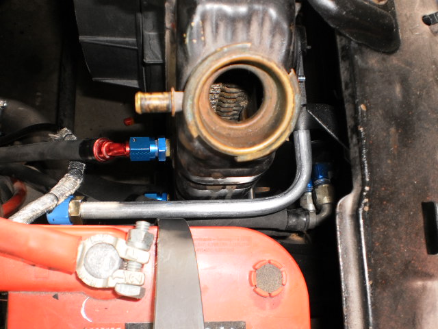
The downsides here besides the fact that I'll have to relocate the coolant recovery are that the 1) the drier is fairly heavier than the heater valve, and 2) I have a fair-sized crack running through the plastic fenderwell in that area.
The solution is to make a cardboard template and transfer it to some 16 ga steel for a reinforcing bracket:
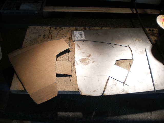
None of the surfaces on the inner fenderwell are actually flat, so it took some massaging to get it molded properly, but four attachment points and some washers on both sides to spread the load make the thing pretty strong.
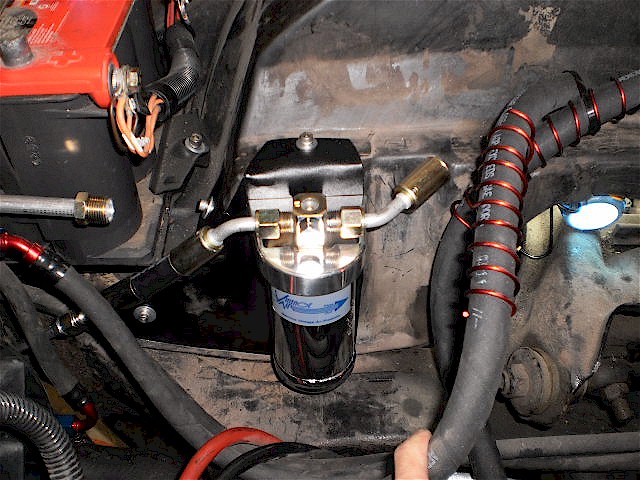
Finally I can start routing hoses. The standard beadlock kit will mostly work here -- the hose lengths are all sufficient, but I will need some additional fittings since not everything lines up as in their diagram. The diagram (and thus the supplied fittings) appear to be designed for the GEN-II unit, and the GEN-IV refrigerant lines come out completely different, so expect that you too will need to purchase additional fittings.
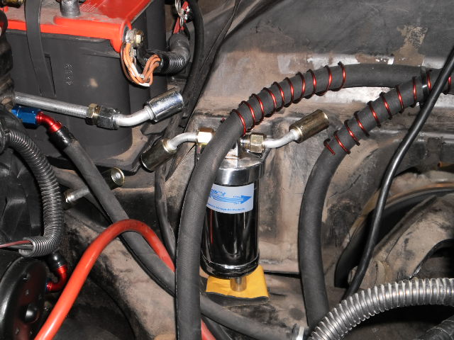
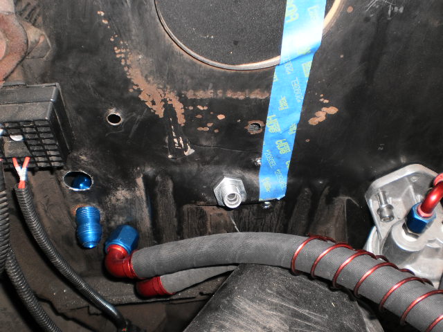
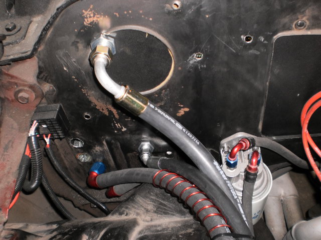
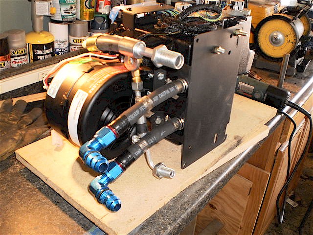
The easiest hose runs were the -6 and -8 from the condenser to the drier and compressor, respectively:
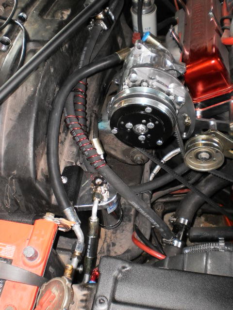
From here we go back the firewall from the drier (-6 supply) and the compressor (-10 suction). I think I have these figured out, but I have to go order some fittings. Stay tuned!
thatfnthing- Donating Member
- Street Cred : 65
Re: Vintage Air Retrofit
![]() by JB2wheeler Sun Jul 08, 2012 6:02 pm
by JB2wheeler Sun Jul 08, 2012 6:02 pm

JB2wheeler- G3GM Fanatic

- Street Cred : 28
Re: Vintage Air Retrofit
![]() by 77mali Sun Jul 08, 2012 9:32 pm
by 77mali Sun Jul 08, 2012 9:32 pm
That's a lot of work...& relocation...can you get a different style coolant bottle? Looks like you have some room on the steering pump side. Keep up the good work!
77mali- Donating Member
- Street Cred : 62
Re: Vintage Air Retrofit
![]() by thatfnthing Wed Jul 11, 2012 12:02 pm
by thatfnthing Wed Jul 11, 2012 12:02 pm
I have been looking at coolant bottles, and they seem to come in all sorts of shapes, sizes, and prices. It'll mostly be a case of figuring out which one will work best. A lot of them are pretty ugly, though, and not all recirculate. Maybe I can find a way to reverse the original and use it on the driver's side...
thatfnthing- Donating Member
- Street Cred : 65
Re: Vintage Air Retrofit
![]() by thatfnthing Mon Jul 23, 2012 8:52 pm
by thatfnthing Mon Jul 23, 2012 8:52 pm
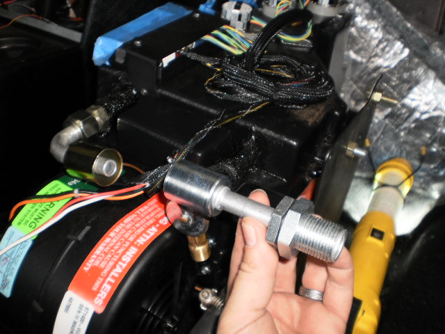
So my fittings arrived, and the first thing I noticed was this:
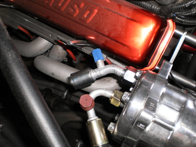
I chose the rear-exit compressor because I was concerned about hood clearance, and the -10 suction fitting has a service port that comes awfully close to the valve cover. Since this one (I believe) will be the one that'll be used to fill the system, I figured I needed more clearance.
I found some hand tools that had shafts that perfectly matched the ID of the fitting on both ends and gently bent another 5 degrees or so into it:
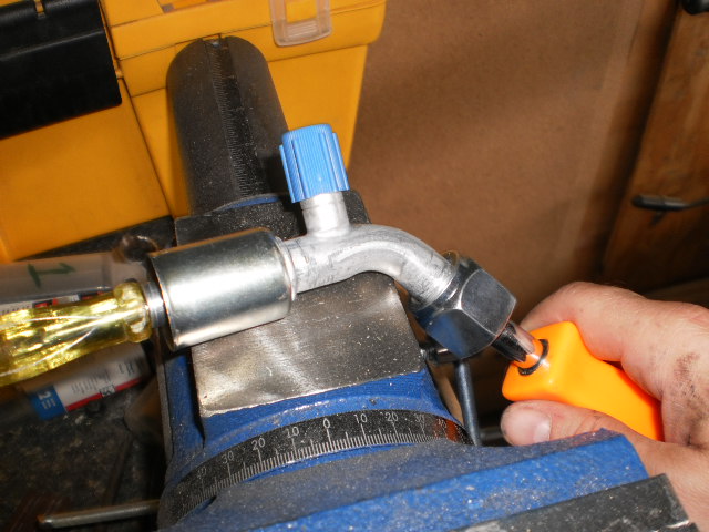
Still not a lot of room, but I'm crossing my fingers that it's enough:
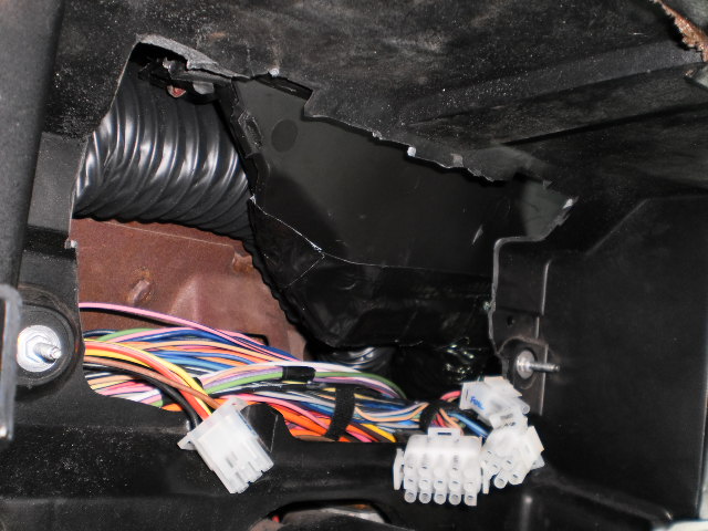
Then I'd reached the moment I'd been dreading: trying to figure out where and how the -10 and -6 lines would come through the firewall from the evaporator. I decided to start with the -10 suction line, which should be easier, since the port comes out of the evap on the glove-box side.
The hose kit comes with a straight evap fitting and a 90* bulkhead fitting, but I needed the exact opposite. A little nail-biting was involved since VA does not list a straight -10 bulkhead fitting in their catalog, but it turned out they have one -- you just have to ask for it.
Here's the evap back in place with the elbow fitting on the -10 port. The marker on the firewall on the cover for the old blower motor is where we're going through. The reason I chose the bulkhead fitting to go this way is because I'm never going to get a wrench in there, so all I have to do is get it through the hole and then I can tighten it down from the engine bay side.
The issue with the -6 supply line stems from the fact that the expansion valve points straight down on the firewall-side of the unit. If that wasn't bad enough, there's only about 2" clearance between the firewall and the evap case. Further, the -10 heater lines are now exactly in the way and the 90* bulkhead fitting will not clear them on a flat firewall surface. The only way I can figure VA expected this to work would be if the evap was located more toward the center of the car, which might allow enough room to run all connections out near the right kick panel. This was not an option for me.
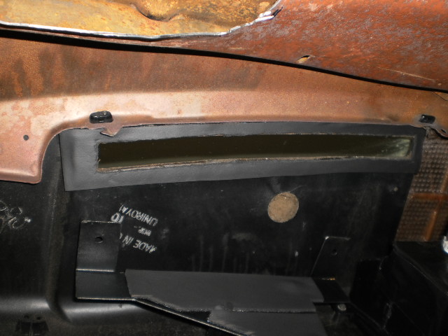
But that's where the car (or more specifically GM) came to my rescue. For no obvious reason there is an indent in the firewall just a couple inches above the floor, right below where the -6 port is on the evaporator:
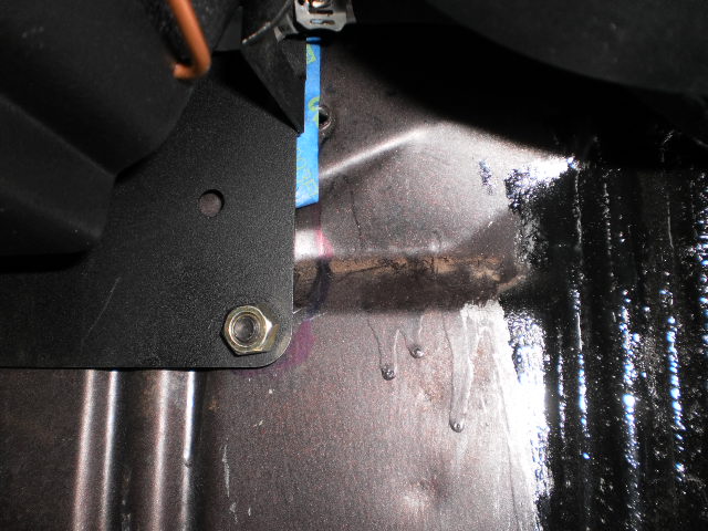
The upper portion of this about a 30* slope and is flat and large enough for a -6 hole:
And if I make this:
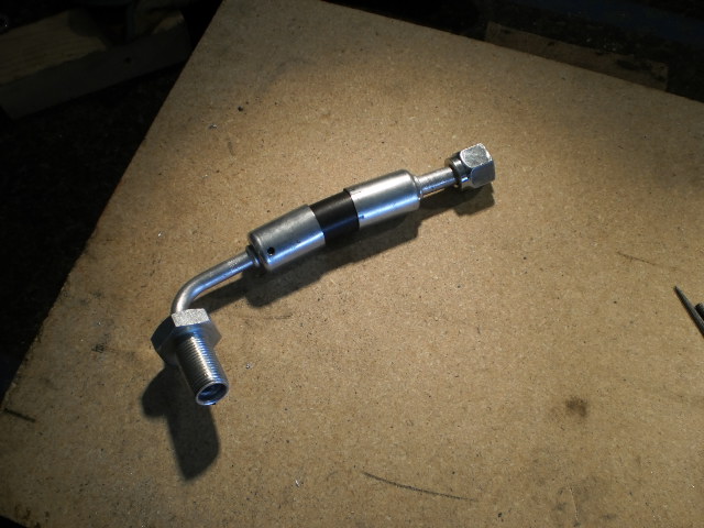
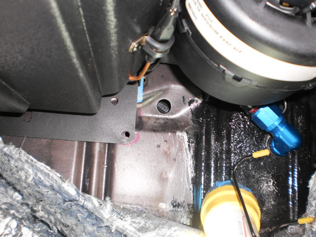
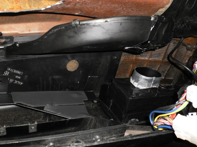
It will make just about a perfect arc around the heater hoses and mount flush against this pad...
...and come out just above the inner fender brace:
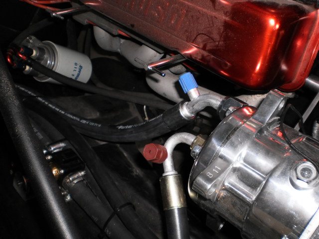
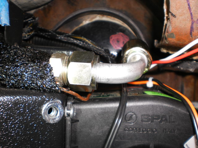
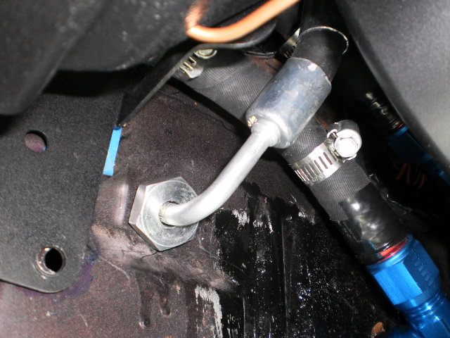
So here are the completed lines on the engine bay side:
And here's how it looks on the evaporator from the firewall side:
I marked how the fittings were oriented on the hoses, so now I just have to find someone locally who can crimp them for me.
Phew! Now I can start putting the dash back together, starting with the ducts.
The defrost ducts hang a bit low IMO, so I put a 1/8" layer of insulation tape on the underside of the dash opening for a better seal on the defrost ducts:
And started putting the modified ducts back in. Here's the previously modified defrost and center ducts:
Next up, controls & wiring!
thatfnthing- Donating Member
- Street Cred : 65
Re: Vintage Air Retrofit
![]() by thatfnthing Mon Jul 23, 2012 10:39 pm
by thatfnthing Mon Jul 23, 2012 10:39 pm
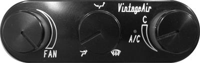
These are pretty expensive -- over $200.00, but I thought they looked decent and they were backlit, which I thought would complement all my gauges. It would have been an acceptable compromise between what I wanted and what I had time for. I would have been a lot happier without the VA logo, though -- If every part I put on the car has the manufacturer's logo on it, it looks like it's a bunch of aftermarket parts slapped together. If there are no logos to be seen, it has more a blended appearance. I will happily give you credit if I use your parts. I don't want to see your logo plastered everywhere you can put it. I want it to look as factory as possible.
However, this is moot, because when I actually received them, it turns out I should have paid closer attention to the dimensions:
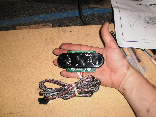
And I don't have overly large hands. These are way too small for the space I have reserved for them in the console. I can see where this makes sense for rodders -- they're working with less real estate, and in a lot of cases they're looking to hide the things altogether. So compactness is a plus for them. However, some of us are looking for something a little more regular-sized.
So a new new idea hatched in my brain, and I'm letting it percolate. A while back I saw an article in Street Rodder where VA had come up with what they called "cable converters" -- basically sliding pots that could be hooked to the old stock factory lever/cable type controls in 60's cars and translate the lever action into an electrical resistance reading to be used by the evaporator's ECM to adjust the fan speed, mode, and temperature. This is actually one of the reasons I chose VA.
However, this is another part that doesn't exactly exist in their catalog. You have to call and ask for the kit from an early Camaro ($99.00):
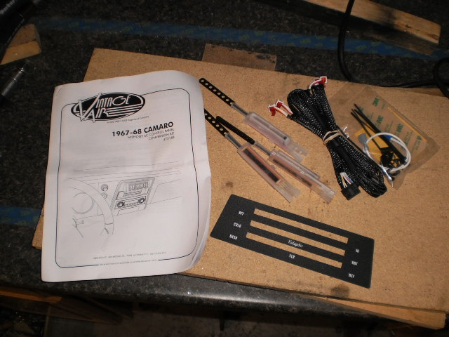
They come with 3 pots, the wiring harness, and instructions on how to set up and calibrate them to the system. While the mounting instructions are specifically for Camaro, with a little effort these could be used to actually convert the stock controls for our cars also.
However, I never do anything the easy way (well, that and I've already discarded the factory controls, which I never liked that much), so I have a different plan.
I have to go talk to some electronics people, and see if I can return the expensive controls.
Stay tuned...
thatfnthing- Donating Member
- Street Cred : 65
Re: Vintage Air Retrofit
![]() by thatfnthing Sun Aug 05, 2012 6:58 pm
by thatfnthing Sun Aug 05, 2012 6:58 pm
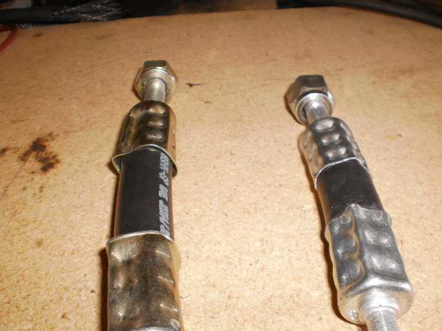
The cad-plated ones (left) gave a much lousier appearance than the custom-ordered fittings (right), surprising the A/C tech also. He feels the crimps are still plenty secure, they just looked like crap. Luckily I'm after reliability more than appearance in this area.
Meantime, let's talk electrical.
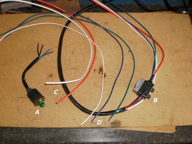
The Gen-IV evaporator comes with a wiring harness and pretty easy-to-follow instructions. Here's the part of the harness on the cabin side:
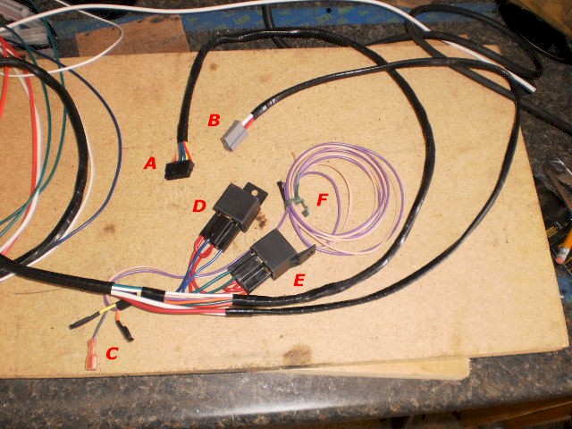
A - Evaporator ECU connection
B - Blower fan power & ground
C - Gray is for programming ECU, orange is for optional WOT switch, and yellow is not used
D - Compressor relay
E - Water valve relay
F - Violet is is 12+ ignition power for the ECU, and tan is noted as for a "dash light" (but no further detail on this is on any of the documentation, like if this is positive or ground)
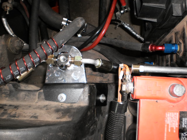
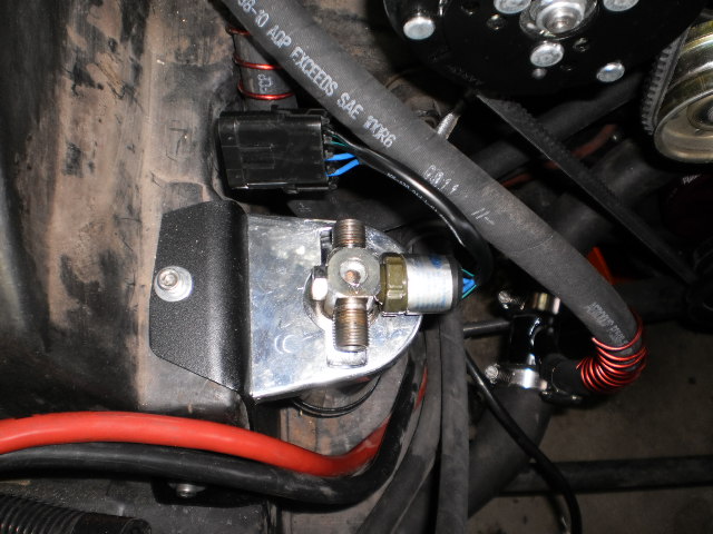
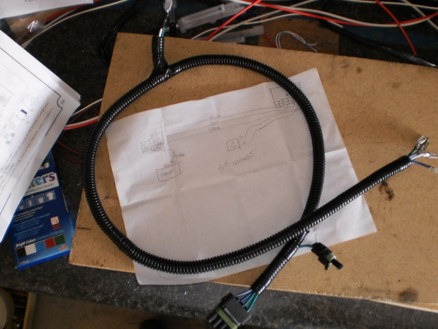
And here's the engine bay side, along with the trinary safety switch I purchased to trigger compressor shutoff and cooling fan engagement:
A - Trinary switch
B - 30A circuit breaker to protect system
C - Battery positive and ground leads
D - White is ECU ground (also goes to battery), while blue is compressor activation and green is water valve activation from their respective relays
Caveat: I upgraded the car's entire electrical system last year to a 93 Caprice wagon, but I knew I'd be putting this unit in, so I made provisions at that time to handle the system through it. Therefore, I will be modifying this harness extensively, but I will try to note where I departed from the VA instructions.
The first variance from the VA plan is to discard the circuit breaker. While circuit protection is an absolute must, I already have a breaker and feed in the fuse panel set aside for this, so I don't need theirs.
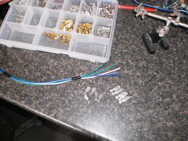
Next, I have to confess I absolutely detest the typical insulated connectors you get with kits like these. While they are easy to use, in my experience they don't fit well, look hideous, and offer no protection from errant moisture, which invites shorting. Consequently, I have a full complement of Weatherpack, Metripack, Pack-Con, and other connectors used in GM vehicles, which give far better better protection and a factory look to boot. Here I put a four contact end on the trinary switch:

I opted for maximum safety to protect the investment here, and that means a trinary safety switch -- it shuts off the compressor if the pressure is either too high or too low, and also provides an override signal for my fan relay to kick on the cooling fans when the compressor is running.
The trinary switch threads into the top of the drier with an O-ring, but you have to be sure to dig out the O-ring that's already in there with the block-off screw -- double O-rings is a guaranteed leak.
On the water valve, however, you only get the standard 1/4" tabs for the electrical connections, so I had no choice but to use the stupid insulated connectors. I gave them a generous amount of electrical tape and am going to hope for the best.
On the compressor we have a butt connector...
...that gets replaced with a WeatherPack connector immediately.
And on the firewall end, I have another type 56/57 block like on the driver's side, so I need to break out the type 56 connectors:
And the resulting harness is complete on the engine bay side. I always make sure to make a diagram, because six months or a couple years later when I'm modifying something again, I won't remember where it all goes.
More to come...
thatfnthing- Donating Member
- Street Cred : 65
77mali- Donating Member
- Street Cred : 62
Re: Vintage Air Retrofit
![]() by thatfnthing Tue Aug 07, 2012 9:08 am
by thatfnthing Tue Aug 07, 2012 9:08 am
77mali wrote:Holy cow...ya lost me @ Trinary
What, you mean everyone doesn't love a good electrical project?
Seriously though, I'm kinda winging this as I go. If something needs more explanation or better photos, let me know while it's still fresh in my mind.
thatfnthing- Donating Member
- Street Cred : 65
Re: Vintage Air Retrofit
![]() by thatfnthing Sun Aug 12, 2012 4:26 pm
by thatfnthing Sun Aug 12, 2012 4:26 pm
I probably mentioned that I don't like any of the choices of controls that VA makes (either too small, too ugly, or both), and I don't intend to use the original Monte controls, either. (A quick note to any VA reps who might read this: you have the street rod market covered pretty well, and the slide pots do well for the vintage market, but you are under-serving the market I'm in -- guys who are trying to update their older rides with modern technology and want a larger, modern looking set of controls.)
So I am about to retrofit modern controls to operate the VA unit.
Now, the guy I spoke to at VA told me specifically that this could not be done, but I'm here to tell (and show) that it can be, and it's not even very difficult if you have a multimeter, basic automotive electrical skill, the documentation for the controls you select, and some patience.
Caveat 1: I have every expectation that I just voided my warranty by doing this, so keep that in mind if you decide to follow this path.
Caveat 2: Be careful! Can't say it enough. Test and re-test. If you provide the wrong voltage to the wrong place, you will burn out something important. You will then be looking at buying new controls or a new ECU for the VA unit.
Okay, here we go:
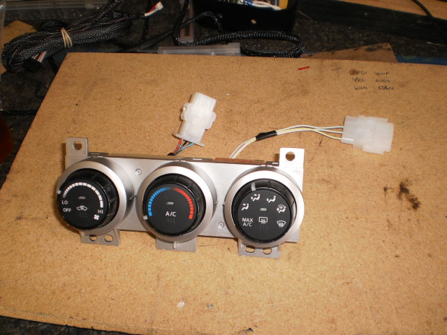
First comes selection. Not all controls will work. I spent considerable time perusing ebay for climate controls, and they come in all shapes and sizes. The controls must mirror the functionality of the VA ones -- i.e. knobs instead of buttons, and the mode selector must go from vent to floor to defrost. This immediately lets out Furd, Saab, and some others, as they have a different order or an Off position in the middle. Obviously design plays a factor also, which let out all of GM -- their stuff looks like it was made by Playskool. Also, I had to have spousal approval
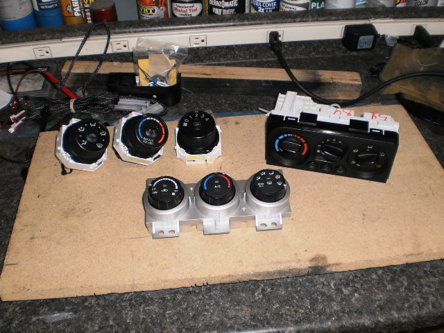
The upper left are from a 2008 Scion XB, and have the advantage of being all electrical and are 3 separate units to facilitate mounting, but didn't have a good "feel" to them. The upper right is from a late-model Subaru Impreza -- these were part electric, part mechanical, which would have taken more work to convert them. They also click louder than my loudest ratchet when you turn the knobs. The bottom ones are from a 2007 Nissan Sentra, and have the right look, feel, and are all electric, so these are what I'm going to use.
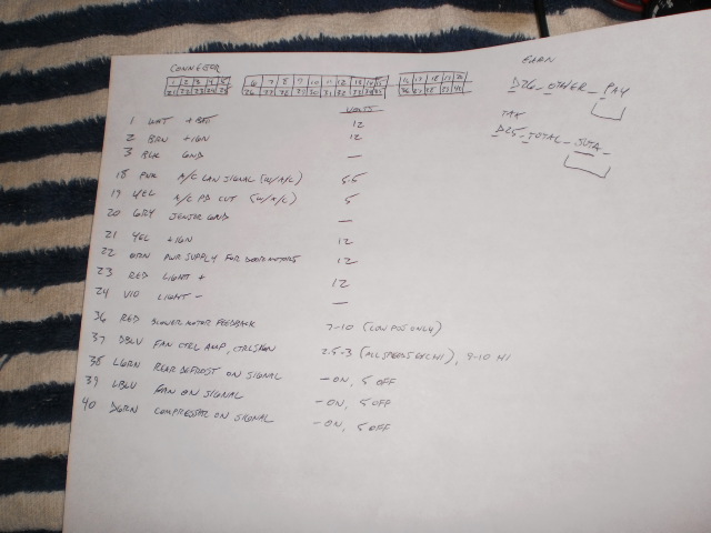
The next step is to track down any factory info on the HVAC from the Sentra, such as wiring diagrams, troubleshooting steps, control assembly, etc. I managed to get my hands on the factory service manual for the 2007 Sentra, which was full of helpful info on what circuit was for what, and even what the voltages would be, so I made myself a handy chart to help my testing:
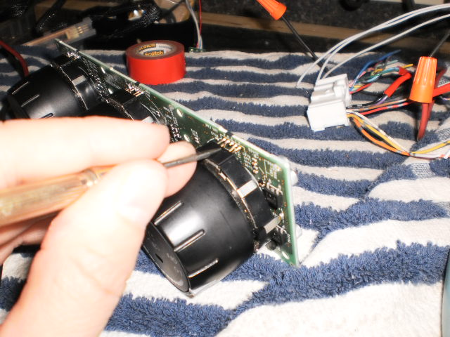
On to disassembly. I always do stuff like this on a towel to keep from scuffing anything.
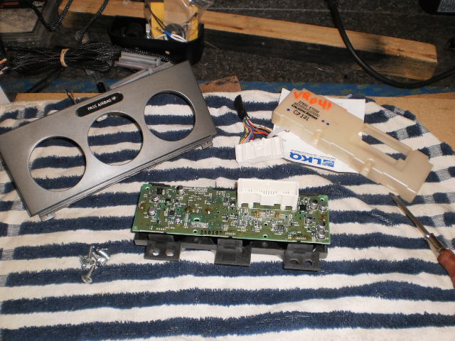
When purchasing anything electrical from a donor car, I learned a long time ago to obtain any electrical connectors wherever possible. Wiring is easy if you have them, and absolute hell if you don't. Goo-Gone works great at getting the goobage off after removing the electrical tape.
Next is to identify the circuits by their position and wire color against the chart and determine which ones I will need. This will also involve plugging it into a 12V power source and testing with a multimeter and for function. Some things were obvious, such as the lighting and the buttons...
...while other things aren't, such as the values from the three knobs. The Nissan controls output a logic value to the car's BCM representing the positions of all three knobs, and the BCM manipulated the actual HVAC from there based on what the controls reported. Therefore, the controls only have one output circuit for all three knobs.
However, the VA unit expects to "see" each knob separately -- it passes a 5V reference to each knob, then reads back the resistance value from that knob's position to make its decision on how to set the door servos in the evaporator.
But I tested the slide pots from the cable conversion kit, as well as the rotary pots from the cheapo controls, and no two units tested at the same resistance values -- i.e. they're all different electrically. Further, the values of the slide pots are in a much greater range than the values of the rotary pots. Yet either can be used with the VA unit, and even mix-n-matched. Couple this with the fact that the VA manual has a step-by-step calibration procedure for "learning" the controls, and it figures that the VA ECU can learn in a fairly wide range. All I should have to do is pass it a value for each knob based on a 5V reference, and it should be able to learn them as if they were VA controls.
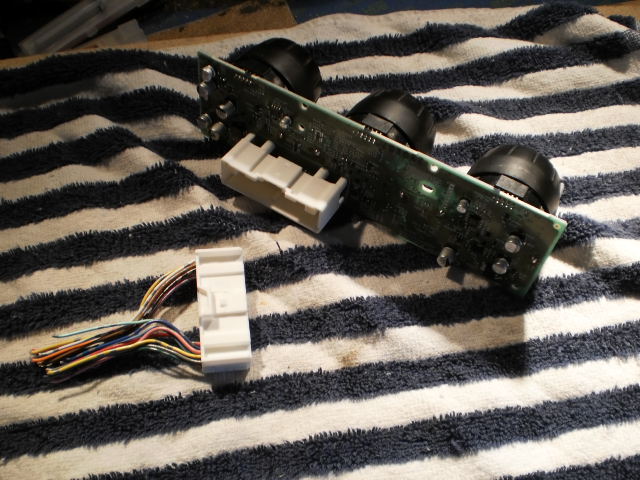
But a little luck never hurts. As it happens, the Nissan controls take a 12V input and steps it down to 5V for the knobs. So all I have to do is use the multimeter to find the "wiper" lead from each knob, which is the one that passes back a variable voltage based on the position of the knob. Turns out it's the third terminal on each knob.
I gently snipped it, bent it outward, and soldered a 22ga lead to it.
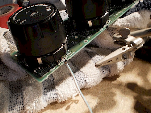
I repeated the process for all three, and color-coded the wires the same as the leads from the VA unit so I didn't mix them up.
Next, a liberal dose of liquid electrical tape to insulate everything.

When dry, I gently wrapped them back around and fed them back out through the back cover of the unit.
Back to the connector -- all leads not being used get a coat of liquid electrical tape also. The ones I will be using (6 total) will get terminals crimped and soldered to them.
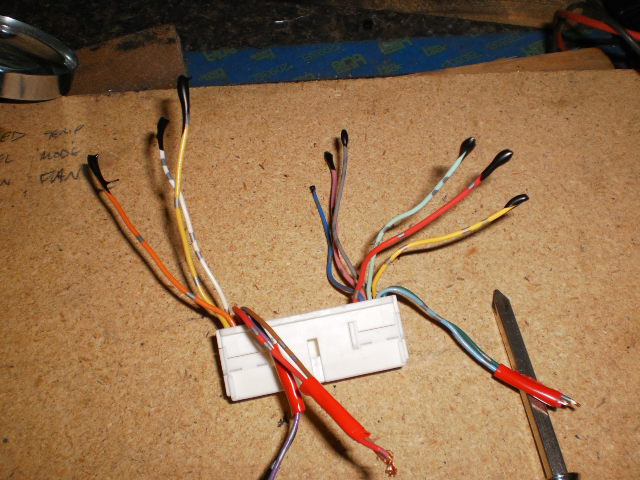
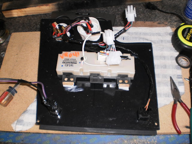
I tested it again one last time, and with 12V coming in, each of the three knobs reads a value between 0V and 4.8V depending on position. I put two separate Molex connectors on it, as the two sets of wires will be going two separate places: the three knob leads to the VA unit, and the others to the main harness for 12V, ground, lighting, and compressor circuits.
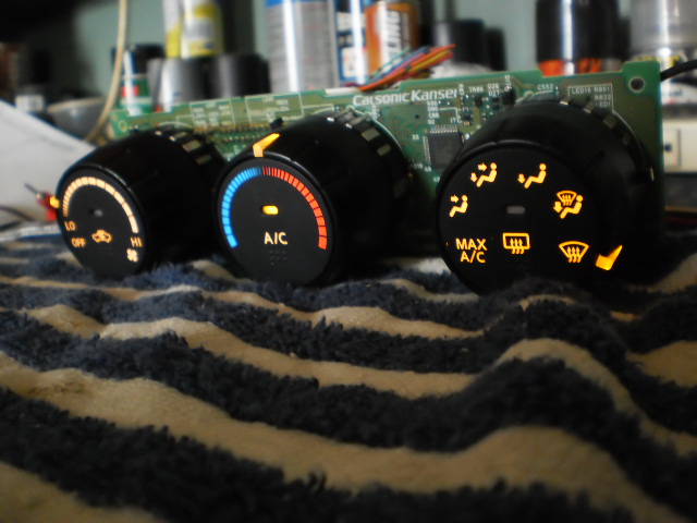
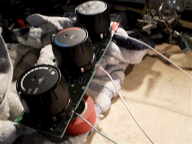
And it works! I don't have the time or skill to post a movie here, so I would ask that you trust me on this one -- in this shot it is actually wired and running, and responding to the controls:
One last trick had to be performed, though: note the small green object to the left of the controls. This is one of the rotary pots from the cheapo VA controls. In order to make the VA ECU "think" it was reading its own controls, I plugged it in to provide the expected resistance just in case. I probably could have just used a 10K ohm resistor (since that was what it tested as), but I didn't have any handy, and this works. Plus, I figured I'd stretched my luck enough for one day.
The calibration procedure didn't go exactly like the instructions said it would, which may be due to the different controls, or that the actual procedure has changed since the instructions were printed. But I waited the specified length of time at each position, and it "learned" successfully. It moves the doors and blows the air out the correct ports as I move the knobs.
Now I can start mounting everything for the last time. Phew!
thatfnthing- Donating Member
- Street Cred : 65

74Malibu383- Donating Member
- Street Cred : 26
Re: Vintage Air Retrofit
![]() by thatfnthing Thu Aug 23, 2012 12:10 pm
by thatfnthing Thu Aug 23, 2012 12:10 pm
thatfnthing- Donating Member
- Street Cred : 65
Re: Vintage Air Retrofit
![]() by thatfnthing Wed Sep 05, 2012 1:03 pm
by thatfnthing Wed Sep 05, 2012 1:03 pm
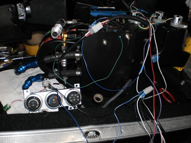
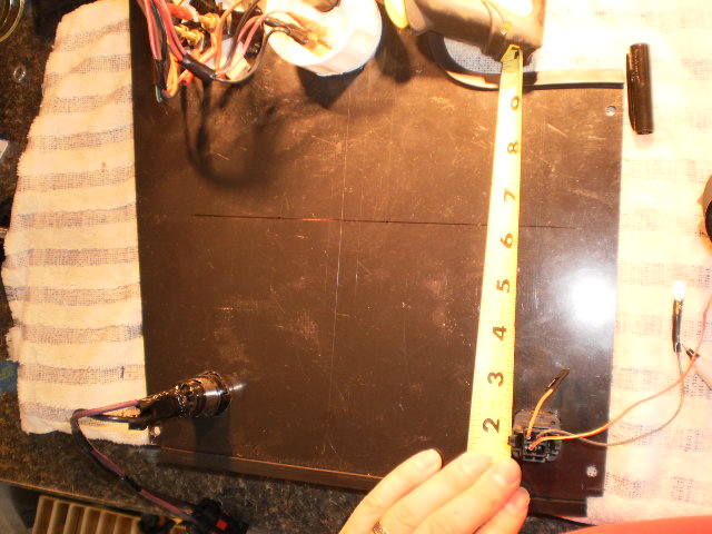
I started by using the original face of the controls to get an idea where I wanted them on the plastic front panel of the console.

Best placement seemed to be about 6 inches above the bottom edge, which leaves me some room for the eventual inverter I plan to add along the bottom. So, flip it over and start drawing the lines to locate the openings.
I slowly (to avoid heat build up and warping) used a hole saw to drill out the holes about 1/8" undersized, then used the Dremel tool with the sanding drum (extra-extra-slowly) to enlarge the holes until the controls fit.
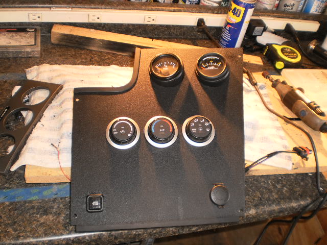
At about this point it seemed to me that from a looks standpoint the larger Scion controls probably would have looked better. To my eye these came out a tad on the plain side -- maybe there's still too much real estate around them. I may go back later and integrate the original control face into this panel to break it up a bit, but for now it will have to do.
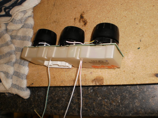
On the flip side, I epoxied some wood blocks under the mounting tabs of the controls, then drilled a short pilot hole in each and used the original screws to secure them.
Just to see what it'll look like, the face gets put back in place in the console temporarily.
I also wrapped up some wiring, which wasn't really conducive to photos, and I started putting things back together under the dash and attaching duct hoses.
Note that while some of my home-brewed adapters obviously require the hose to be duct taped to ensure the hose stays attached, the VA stuff will have "ears" to snag the hose. These are insufficient to retain the hose, and also the hose seal is not tight, so you will be best off taping these also.
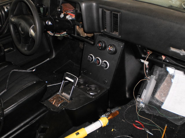
Left defrost duct:
The hose behind the duct is actually the feed for the left dash vent:
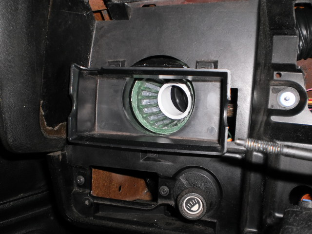
Since my electrical upgrade last year consumed a lot of the space below the dash on the left side, there wasn't really room for the hose to go beneath or to use the conduit attached to the crotch vent. Luckily I was able to squeeze it in behind the defrost duct.
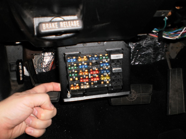
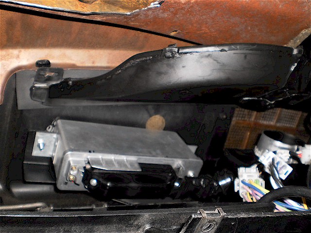
Right defrost duct and ABS computer:
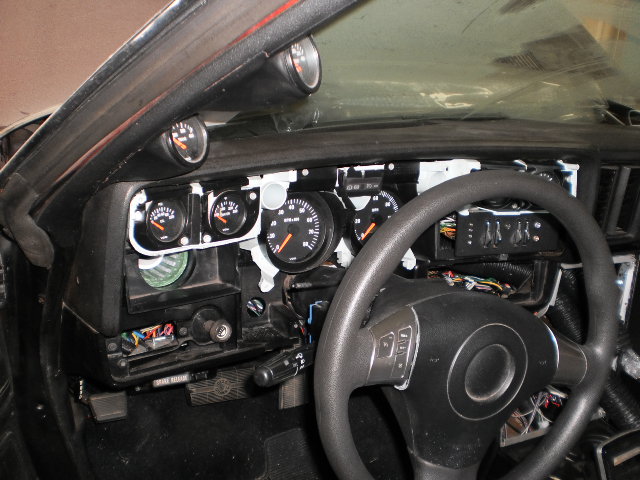
And now I can put the instrument cluster back:
More to come...
thatfnthing- Donating Member
- Street Cred : 65
Re: Vintage Air Retrofit
![]() by 77mali Wed Sep 05, 2012 4:15 pm
by 77mali Wed Sep 05, 2012 4:15 pm
77mali- Donating Member
- Street Cred : 62
Re: Vintage Air Retrofit
![]() by thatfnthing Thu Sep 06, 2012 1:30 pm
by thatfnthing Thu Sep 06, 2012 1:30 pm
thatfnthing- Donating Member
- Street Cred : 65
Page 2 of 4 • 1, 2, 3, 4 ![]()


|
|
|
» 1973 4 door laguna frame same as 1973 2 door chevelle
» Dash assembly for 73-77 Malibu/Monte/El Camino,etc.
» Window louvers
» 1973 Chevelle SS 1 Family
» 1973 Chevelle SS, 350, 4spd. build
» Who works on 73-77 "soft" steering wheels?
» Blue door jamb sticker
» Factory am/fm
» Factory am/fm