


How I Did It: Rear Suspension Modifications
+4
Keith Seymore
thatfnthing
BBMALIBU
Dinomyte
8 posters
Page 1 of 1

How I Did It: Rear Suspension Modifications
![]() by Keith Seymore Mon May 11, 2015 12:39 pm
by Keith Seymore Mon May 11, 2015 12:39 pm
I had a request to post up some pictures and describe the rear suspension changes that I have made to my car. It’s fairly involved so I’ll try walking though it here:
Unfortunately (…or fortunately, depending on your perspective) there’s kind of a lot going on here, so we need to back up a bit before we get into the suspension proper.
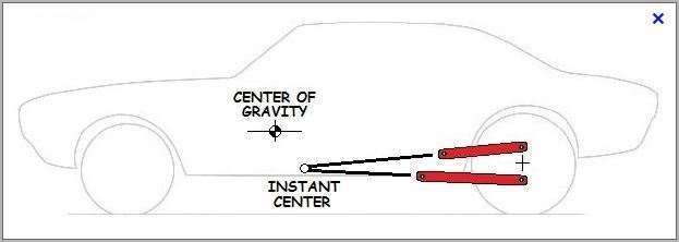
I sort of brought this upon myself but this was all precipitated by breaking the upper control arm attaching points in the rear suspension crossmember. I had re-drilled the attaching holes to emulate the instant center position of an “anti-hop” bar. I allowed for clearance in full jounce (downward) travel by providing a notch in the lower flange of the crossmember; unfortunately that created a stress riser and the crossmember split in that area. Multiple attempts to repair it locally were only temporarily successful and at that point Dad and I decided the body needed to come off the frame to do it right.

Naturally, since we had just the frame sitting there, all out in the open, we decided this would be a good time to “back half” the car too - sort of – by narrowing the rear section of the frame, using all production components.
We set the bare frame up on a makeshift surface plate. All of the crossmembers were removed (trans – just as a matter of disassembly; rear suspension – to facilitate the narrowing; rear crossmember removed previously for weight savings) so that the frame rails were just floppy appendages sticking into space rear of the engine bay.
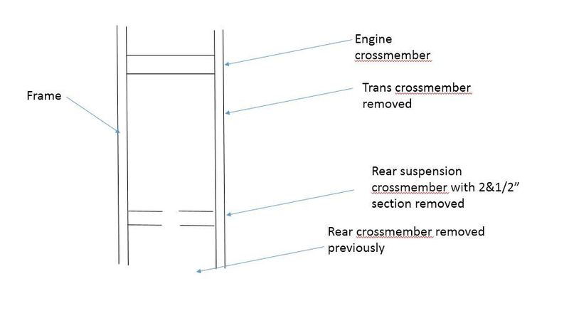
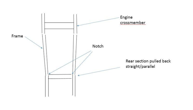
We pulled the frame rails together until the rear suspension crossmember pieces touched in the middle, resulting in a 2.5” narrower section in that area. Notches aft of the engine bay were welded back up at that point to help control the change.

We then pulled the rear legs of the rails back straight (parallel), making the rear portion of the frame square once again. Once we were satisfied dimensionally then the hole thing was welded back up, esentially moving the rails inboard 1.25” per side. The body wheel house was still inboard of this point, so the frame change allowed the installation of a 29.5x15.5 Mickey Thompson Pro Sportsman tire (13.5” wide) on a 10” wheel with no body modification.
Naturally that meant that all new body mounts and suspension attatching points had to be fabricated. We elected to straighten all of the control arms in the plan view, resulting in essentially a “race car” four link rear suspension but with production components. A “fifth link”, a panhard bar, was added to control the rear axle laterally as a result.
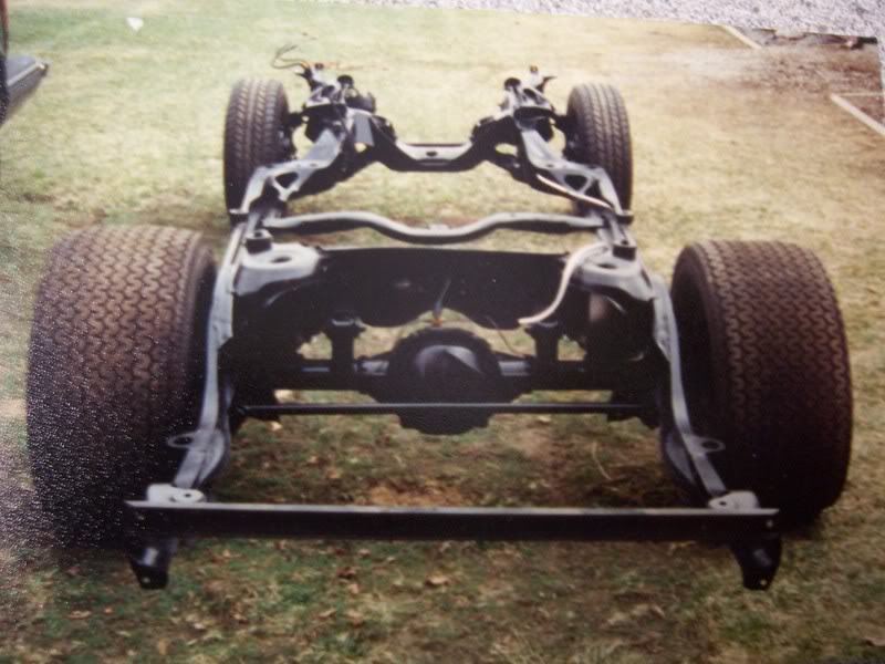
In this front view you can see the angle braces added to help prevent a similar reoccurance.
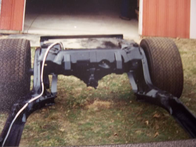
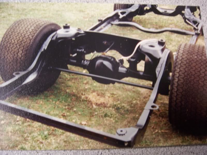
You can see pieces of PVC pipe in place of the rear springs, to simulate the proper ride height. You can see the control arm attaching points added to the axle tube, moving them off the differential housing and straightening them up in the plan view.
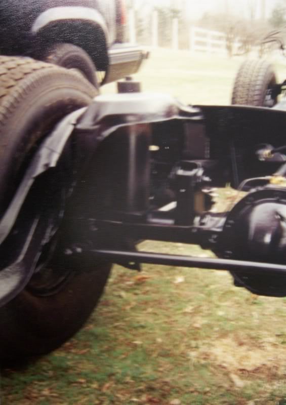
A temporary rear crossmember is visible in these last two pics. The steel rear bumper functions as the rear crossmember when everything is installed.
This is a good time to add a 1/2" fuel line, too.
Unfortunately (…or fortunately, depending on your perspective) there’s kind of a lot going on here, so we need to back up a bit before we get into the suspension proper.
I sort of brought this upon myself but this was all precipitated by breaking the upper control arm attaching points in the rear suspension crossmember. I had re-drilled the attaching holes to emulate the instant center position of an “anti-hop” bar. I allowed for clearance in full jounce (downward) travel by providing a notch in the lower flange of the crossmember; unfortunately that created a stress riser and the crossmember split in that area. Multiple attempts to repair it locally were only temporarily successful and at that point Dad and I decided the body needed to come off the frame to do it right.
Naturally, since we had just the frame sitting there, all out in the open, we decided this would be a good time to “back half” the car too - sort of – by narrowing the rear section of the frame, using all production components.
We set the bare frame up on a makeshift surface plate. All of the crossmembers were removed (trans – just as a matter of disassembly; rear suspension – to facilitate the narrowing; rear crossmember removed previously for weight savings) so that the frame rails were just floppy appendages sticking into space rear of the engine bay.
We pulled the frame rails together until the rear suspension crossmember pieces touched in the middle, resulting in a 2.5” narrower section in that area. Notches aft of the engine bay were welded back up at that point to help control the change.
We then pulled the rear legs of the rails back straight (parallel), making the rear portion of the frame square once again. Once we were satisfied dimensionally then the hole thing was welded back up, esentially moving the rails inboard 1.25” per side. The body wheel house was still inboard of this point, so the frame change allowed the installation of a 29.5x15.5 Mickey Thompson Pro Sportsman tire (13.5” wide) on a 10” wheel with no body modification.
Naturally that meant that all new body mounts and suspension attatching points had to be fabricated. We elected to straighten all of the control arms in the plan view, resulting in essentially a “race car” four link rear suspension but with production components. A “fifth link”, a panhard bar, was added to control the rear axle laterally as a result.
In this front view you can see the angle braces added to help prevent a similar reoccurance.
You can see pieces of PVC pipe in place of the rear springs, to simulate the proper ride height. You can see the control arm attaching points added to the axle tube, moving them off the differential housing and straightening them up in the plan view.
A temporary rear crossmember is visible in these last two pics. The steel rear bumper functions as the rear crossmember when everything is installed.
This is a good time to add a 1/2" fuel line, too.
Last edited by Keith Seymore on Mon May 11, 2015 1:02 pm; edited 3 times in total
Keith Seymore- G3GM Member

- Street Cred : 11
Re: How I Did It: Rear Suspension Modifications
![]() by Keith Seymore Mon May 11, 2015 12:45 pm
by Keith Seymore Mon May 11, 2015 12:45 pm
I should perhaps take a second to talk about this makeshift "surface plate". Calling it a surface plate might be a bit generous.
I can't find my pictures but what we did was set the frame up on 4 RV screw type jack stands. The stands were placed at four points on the frame and adjusted until the frame was level fore/aft and side to side.
The rear portion of the frame was set on a piece of "U" channel, with the U facing up. This allowed the frame sections to slide inboard with a minimum amount of friction. Truth be told, they were quite floppy but we used a piece of threaded rod to make the pull in a more controlled fashion, measuring to within .1" to make sure the amount was even per side and the resulting work square to the world.
K
Keith Seymore- G3GM Member
- Street Cred : 11
Re: How I Did It: Rear Suspension Modifications
![]() by Keith Seymore Mon May 11, 2015 12:56 pm
by Keith Seymore Mon May 11, 2015 12:56 pm
Shortly after finishing all this work I was restricted to a 10.5" tire (or 10.5W) by the class rules so none of the narrowing work really mattered.
The pen truly is mighter than both the sword and the wrench.

The pen truly is mighter than both the sword and the wrench.
Last edited by Keith Seymore on Mon May 11, 2015 1:26 pm; edited 1 time in total
Keith Seymore- G3GM Member
- Street Cred : 11
Re: How I Did It: Rear Suspension Modifications
![]() by Dinomyte Mon May 11, 2015 1:16 pm
by Dinomyte Mon May 11, 2015 1:16 pm
That's so ingenious.
Dinomyte- Donating Member

- Street Cred : 11
Re: How I Did It: Rear Suspension Modifications
![]() by BBMALIBU Mon May 11, 2015 1:31 pm
by BBMALIBU Mon May 11, 2015 1:31 pm
First, thank you very much for posting the mod's you and your father did.
Second, would the DickMillerRacing support braces have prevented the crossmember/upper control arm mounting point from breaking? Since DMR states that this support bar will prevent this point from breaking.
Third...WOW that's a lot of work.
Second, would the DickMillerRacing support braces have prevented the crossmember/upper control arm mounting point from breaking? Since DMR states that this support bar will prevent this point from breaking.
Third...WOW that's a lot of work.
BBMALIBU- G3GM Member
- Street Cred : 2
Re: How I Did It: Rear Suspension Modifications
![]() by Keith Seymore Mon May 11, 2015 2:03 pm
by Keith Seymore Mon May 11, 2015 2:03 pm
BBMALIBU wrote:First, thank you very much for posting the mod's you and your father did.
Second, would the DickMillerRacing support braces have prevented the crossmember/upper control arm mounting point from breaking? Since DMR states that this support bar will prevent this point from breaking.
Third...WOW that's a lot of work.
Thank you (both).
Any bar that bolted through the suspension attaching point might have helped. Anything that bolted or was welded to the bottom flange (like what I have now) surely would have helped.
Yes - that was a lot of work. It was down for a couple seasons; my youngest son turned two and I realized the car had never been together during his lifetime. I cleared my calendar and flailed to get it back together. I hope to never have anything that far apart ever again.
K
Last edited by Keith Seymore on Tue May 12, 2015 7:07 am; edited 1 time in total
Keith Seymore- G3GM Member
- Street Cred : 11
Re: How I Did It: Rear Suspension Modifications
![]() by thatfnthing Mon May 11, 2015 2:44 pm
by thatfnthing Mon May 11, 2015 2:44 pm
Wow, that's impressive stuff. Couple Q:
1) There seems to be a fair amount more tire-to-frame clearance on the right side than the left. Is this by design, a trick of the camera, or just something I missed in your write-up?
2) Do the broken rod and piston have anything to do with this story, or do you just keep a collection of the broken stuff around to reminisce?

thatfnthing- Donating Member
- Street Cred : 65
Re: How I Did It: Rear Suspension Modifications
![]() by Keith Seymore Mon May 11, 2015 2:46 pm
by Keith Seymore Mon May 11, 2015 2:46 pm
thatfnthing wrote:Wow, that's impressive stuff. Couple Q:
1) There seems to be a fair amount more tire-to-frame clearance on the right side than the left. Is this by design, a trick of the camera, or just something I missed in your write-up?
2) Do the broken rod and piston have anything to do with this story, or do you just keep a collection of the broken stuff around to reminisce?
1) Good eye. The wider combination is mounted on a 15x10" wheel (with the 2" added to the back side). The narrower tire is mounted to a stock 15x8 Corvette rally, not yet widened.
2) Yes - you've had a peek into the "Broken Parts Display". There are many stories hiding in there.
K
Keith Seymore- G3GM Member
- Street Cred : 11
Re: How I Did It: Rear Suspension Modifications
![]() by dynchel Mon May 11, 2015 5:07 pm
by dynchel Mon May 11, 2015 5:07 pm
That's cool, I didn't know you modified that much. Thanks for posting.

dynchel- Donating Member
- Street Cred : 40
Re: How I Did It: Rear Suspension Modifications
![]() by Roadcaptain S3 Mon May 11, 2015 5:26 pm
by Roadcaptain S3 Mon May 11, 2015 5:26 pm
Wow! Thanks.

Roadcaptain S3- Donating Member
- Street Cred : 26
Re: How I Did It: Rear Suspension Modifications
![]() by pila Mon May 11, 2015 7:00 pm
by pila Mon May 11, 2015 7:00 pm
Nice work ! The instant center makes a lot of sense for sure ! That was discussed here a couple years ago also.
Thanks for laying it out for us !
Bill
Thanks for laying it out for us !
Bill
pila- Donating Member
- Street Cred : 43
Re: How I Did It: Rear Suspension Modifications
![]() by bracketchev1221 Tue May 12, 2015 5:44 am
by bracketchev1221 Tue May 12, 2015 5:44 am
That definitely is some thought out work. Good job.
bracketchev1221- G3GM Enthusiast

- Street Cred : 15

 Similar topics
Page 1 of 1
Permissions in this forum:
You cannot reply to topics in this forum|
|
|
» 76 Laguna parked in 2002
» El Camino/Sprint LH Aftermarket Quarter Panel FOR SALE
» dashes
» Thanks for having me
» 77 elco SS
» 3-g cars in Finland
» Stainless brake lines
» New chassis for my 73
» 1973 Chevelle SS, 350, 4spd. build